I. Case Background: A Power System of “Small Horse Pulling a Heavy Load”
I recently took in an electric vehicle controller for repair with the following specifications:
- Controller: 72V, 400A (peak)
- Motor: 7.5 kW rated, 15 kW peak, peak torque 110 N·m
- Gear ratio: 10.5 : 1
- Tire radius: 355 mm
- Gross vehicle weight: 2000 kg
- Designed vehicle speed: 40 km/h
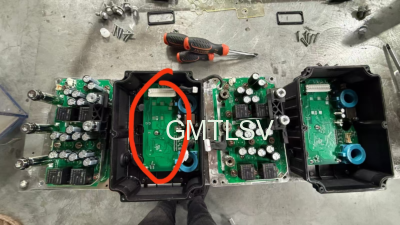
Customer complaint: The controller’s MOSFETs burned out and the vehicle could not drive. Two controllers of the same model were delivered for repair. One had an intact control board but a damaged aluminum‑base circuit board; the other had a sound aluminum‑base circuit board but a faulty control board. The customer wanted to swap the aluminum‑base boards to assemble one functional controller.
This repair approach is fairly common among technicians, yet this case turned out to be far more complicated.
II. Performing Power Calculations: How Much Power Is Actually Required for Level‑Ground Cruising?
Many repair technicians see “72V 400A” paired with a “7.5 kW motor” and assume ample power reserve. However, real‑world loading must be evaluated using fundamental physics formulas.
Vehicle speed 40 km/h = 11.11 m/s. Tire radius 0.355 mm yields a wheel speed of approximately 299 RPM and a motor speed of roughly 3140 RPM.
For a 2‑ton vehicle cruising at constant speed on level ground, only rolling resistance and aerodynamic drag need to be overcome:
- Rolling resistance: 2000 × 9.8 × 0.012 ≈ 235 N
- Aerodynamic drag: approximately 159 N
- Total tractive force: approximately 394 N
Wheel‑end power requirement: 394 × 11.11 ≈ 4.4 kW. Accounting for transmission and motor efficiency (85 %), the required motor output is around 5.2 kW.
Converted to controller DC‑bus side: 5.2 kW ÷ 0.95 ÷ 72 V ≈ 76 A.
Clear conclusion: At 40 km/h level‑ground cruising, the controller only outputs 76 A, and the motor develops merely 15.7 N·m torque — less than 15 % of its 110 N·m peak rating. Under these operating conditions, MOSFET heating is minimal, and burnout cannot occur.
III. Root Cause of MOSFET Failure: Low‑Speed Heavy‑Load and Hill‑Climbing Over‑Current
Since level‑ground operation presents no risk, MOSFET burnout must happen during transient operating conditions. Let us analyze hill‑climbing scenarios.
For a gentle 5° grade (~8.7 % slope): slope resistance = 2000 × 9.8 × sin 5° ≈ 1705 N. Adding the level‑ground resistance of 394 N gives total resistance of roughly 2100 N. The corresponding wheel‑end power demand reaches approximately 23.3 kW, motor power around 27.4 kW, and DC‑bus current hits 380 A, nearly touching the 400 A current‑limit setting.
An even more hazardous condition is heavy‑load low‑speed start‑up. When the fully‑loaded vehicle launches from rest on an incline or gets stuck, motor rotational speed stays very low. To deliver high torque, the FOC algorithm produces phase‑current peaks 1.5‑2 times the DC‑bus current, meaning 600‑800 A flows through the MOSFETs. MOSFET conduction loss follows the formula $P=I^2\times R_{DS(on)}$, rising exponentially. Junction temperature can exceed the 150 °C thermal limit within seconds, causing catastrophic MOSFET failure.
Therefore, MOSFET burnout does not stem from poor‑quality devices. Instead, the system operates persistently near its absolute performance boundary with insufficient power margin.
IV. Swapping Aluminum‑Base Circuit Boards: It May Work — But Only Under Prerequisites
The customer’s proposed aluminum‑board swap is theoretically feasible. Combining a good control board with a good aluminum‑base board from two broken units can yield one working controller.
Nevertheless, all of the following prerequisites must be satisfied:
- The two controllers share identical model numbers and hardware revisions, including matching MOSFET part numbers, drive circuitry, and sense resistors.
- Verify that the “good aluminum‑base board” is genuinely undamaged: no degraded MOSFETs, no cracked solder joints, and intact gate‑drive resistors.
- The control board and aluminum‑base board must be electrically compatible: consistent gate‑drive voltage, dead‑time settings, and over‑current protection thresholds.
- Apply high‑performance thermal compound and fasten mounting screws with uniform torque to guarantee adequate heat dissipation.
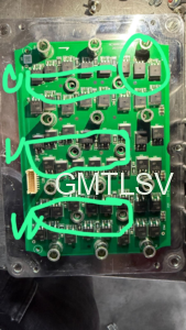
In this real‑world repair, after installing the supposedly functional aluminum‑base board, the controller still failed to operate. This strongly suggests the presumed‑good board contained latent defects. Repeating the swap without clear diagnostic photographs will merely cause repeated device burnout.
V. Key Points for Customer Communication
Repair work is not simple component replacement; consensus must be built with the customer. Three critical messages were emphasized to the customer in this case:
First, trouble‑free level‑ground driving does not indicate a healthy system. While cruising draws only 76 A, hill‑climbing or launch events can push instantaneous current to 400 A, exposing fundamental system‑design limitations.
Second, clear photographs of the spare aluminum‑base board are mandatory. Inspect for surface cracking on MOSFETs, discolored or lifted solder joints, and damaged gate‑drive resistors. Without visual evidence, board integrity cannot be confirmed.
Third, post‑repair software current‑limit adjustment is recommended. Limit stall / launch current to approximately 250 A. Accept somewhat reduced peak acceleration in exchange for improved MOSFET reliability. Optimize dead‑time parameters to prevent shoot‑through between upper‑arm and lower‑arm switches.
VI. Repair Recommendations for Technicians
- Calculate real‑world loading before repairing hardware. Do not rely solely on controller nameplate current ratings; analyze vehicle mass, operating speed, and gear ratio to establish actual system demands.
- Whenever MOSFETs burn out, always inspect the drive circuitry. Insufficient gate‑drive voltage, inadequate dead‑time, or abnormal gate resistance can cause partial MOSFET turn‑on or shoot‑through faults.
- Exercise caution when swapping aluminum‑base boards. Measure for MOSFET drain‑source short‑circuits and verify gate‑drive waveforms from the control board before power‑on testing.
- Thermal management is critical for reliability. Thermal interface compound, screw torque, and heat‑sink area are all details that determine success or failure under high‑current operation.
- Software current‑limiting acts as the final safety barrier. Where hardware power margin is insufficient, current must be constrained in firmware. Otherwise repeated MOSFET replacement will never resolve the underlying failure mode.