

In the world of automotive electronics and industrial control, CAN bus is like an invisible neural network, which connects various control units (ECU) closely.
The DBC file is the “language dictionary” of the network-it records what and how each node says, and understanding the DBC file is a necessary skill.
What is a DBC file
DBC (Database CAN) is a CAN network data file, which is a common standard format file.
To simply understand the use of DBC, the contents in the DBC file can help us understand the CAN network nodes and interactive information, and provide the parsing methods and definitions of messages and signals.
How to open a DBC file
DBC files (.dbc format) can be opened with Notepad or with professional tools such as CANoe
The CANdb + + software in can also be opened by self-developed software tools. The sample files opened with Notepad are as follows:
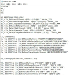
How content in a DBC file is par
Learn the DBC file content and document content from the file content structure and explanation, and introduce the following contents:
- Versions and new symbols
The DBC file header contains the “version” and “new symbol” information
(1) The “version” version information can be null.
(2) “new symbol” symbol information
2.Baud rate definition
BS _ is a keyword used to define the baud rate of the CAN network
- Definition of network nodes
BU _ is the keyword, indicating the network node, and the node name shall be unique
- Definition of message frame
(1) BO _ is a keyword, indicating the message;
(2) MessageId is the defined message ID, which is represented by decimal number.
(3) MessageName indicates the name of the message;
(4) Message Size represents the number of bytes in the data domain of the message, which is unsigned integer data;
(5) Transmitter represents the network node that sends the message.
- Definition of signal
Format: SG _ CEM _ BMSIdentifyTimout: 0 | 2 @ 1 + (1,0) [0 | 1] “” Vector _ _ XXX
(1) SG _ is a keyword, indicating the signal;
(2) SignalName: CEM_BMSIdentifyTimout;
(3) 0 | 2 indicates that the start bit is 0 and the signal length is 2; @ 1 indicates Intel format and @ 0 indicates Motorola format;
(4) + represents a numeric type, + represents an unsigned number, and-represents a signed number;
(5) (1,0) indicates that the scale factor is 1 and the signal offset is 0;
Calculation method of actual physical value of signal: actual physical value of signal = original value (decimal system) * factor + offset;
(6) [0 | 1] indicates that the minimum value of the signal is 0 and the maximum value is 1;
(7) “” indicates the unit of the signal, which is a string type;
(8) Vector _ _ XXX represents the receiving node of the signal; if the signal has no designated receiving node, it must be set.
Is the Vector _ _ XXX “.
SG _ CEM _ BMSIdentifyTimout as in example: 0 | 2 @ 1 + (1,0) [0 | 1] “” Vector _ _ XXX
Indicates that a signal named as timeout of receiving BMS identification message is defined. The start bit is the 0th bit, and the signal length is 2 bits; the signal is in Intel format, and the value type is unsigned number; the scale factor is 1, and the offset is 0; the signal value range is 0 to 1; the signal unit is null; The signal receiving node has no.
- Annotations
The CEM _ BMSIdentifyTimout “of the CM _ SG _ 2283795542 receives the identification message of the BMS and the vehicle” timeout “;
(1) CM _ is a keyword, indicating annotation information;
(2) The SG _ 2283795542 indicates the SG _ “CEM _ BMSIdentifyTimout of the 2283795542 message under the frame ID for annotation, and the annotation is: timeout for receiving the identification message of the BMS and the vehicle;
- Attribute definition part (can be researched by network search)
BA_ “GenMsgCycleTime” BO_ 2283795542 250;
(1) a BA _ DEF _ is a keyword and represents an attribute definition;
(2) Object represents the object type defined by the attribute, which can be node “BU _” “, message” BO _ “”, message “SG _” “, network node” ” (represented by blank space), etc.;
(3) AttributeName indicates the name of the attribute to be defined;
(4) ValueType indicates the type of the attribute value, which can be integer, string, floating point type, enumeration type, etc.;
(5) Min/Max indicates the maximum and minimum values of the attribute value, that is, the value range is specified (the string type does not have this item).
(6) the BA _ DEF _ DEF _ is a keyword and represents the initial value of the defined attribute;
(7) DefaultValue represents the initial value of the attribute.
- Interpretation of signal values
VAL _ 2283795542 CEM _ BMSIdentifyTimout 2 “Untrusted” 1 “Timeout” 0 “OK”;
(1) VAL _ is a keyword, indicating the definition of the value table;
(2) The 2283795542 indicates the message ID to which the signal belongs (in decimal notation);
(3) that CEM _ BMSIdentifyTimout indicate the name of the signal;
(4) 2 “Untrusted” 1 “Timeout” 0 “Normal” indicates the content of the defined value table, that is, what symbol is used to represent the effective value of the signal.
The DBC file is the cornerstone of CAN network development and debugging, but it is not the end. In real projects, you will also encounter DBC-based code generation, integration of diagnostic protocols such as UDS, and more complex network management. Keep in mind, however, that all advanced applications are based on a deep understanding of DBC files.


