

Background
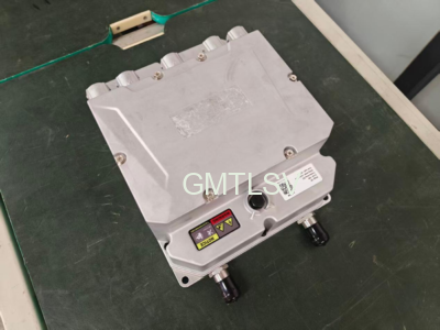
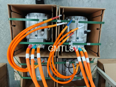
Recently, a customer in South Africa purchased a sample unit of our 96V 15kW PMSM motor drive systemfor validation on a 16-seat electric sightseeing shuttle. After the customer completed mechanical installation and electrical wiring, the project moved into the commissioning phase. It didn’t take long before feedback came in: the throttle response was laggy and disconnected from driver input, making speed control difficult and imprecise.
While “laggy throttle” is a common complaint in EV commissioning, those three words can point to several different root causes. With no option to test-drive the vehicle ourselves, we had to rely on remote communication and parameter analysis. Below is a full walkthrough of the troubleshooting and optimization process.
Issue 1: Delayed Throttle Response and Poor Controllability
Symptom Description
The customer described the issue vividly:
- Noticeable delay between pressing the accelerator pedal and power delivery;
- Minimal speed change when making fine adjustments to the pedal position;
- Overall sluggish feel—unlike a combustion engine vehicle where the car goes exactly as much as you press.
Troubleshooting Approach
Since the customer had already completed basic installation, and there were no fault codes related to motor phasing, resolver/encoder signals, or wiring, the underlying drive hardware was ruled out. We shifted focus to throttle mapping parameters in the controller’s configuration software.

The controller’s throttle configuration includes the following key parameters:
| Parameter | Function |
| Throttle Deadzone Voltage | Below this voltage, throttle is treated as fully released |
| Throttle 25% Output | Output percentage corresponding to 25% throttle opening |
| Throttle 50% Output | Output percentage corresponding to 50% throttle opening |
| Max Throttle Voltage | Voltage value at full pedal travel |
| Throttle Offset Output | Default output at zero pedal position (prevents creep or jerk) |
Optimization Plan
We made the following adjustments:
① Lowered the throttle deadzone voltage
The original deadzone was set too high, causing the initial pedal travel to be completely ignored. By lowering the deadzone threshold, power delivery kicked in earlier, eliminating the “dead travel” sensation where nothing happened after initially pressing the pedal.
② Reduced low-range throttle output ratios
- Throttle 25% Output: changed from 25% → 15%
- Throttle 50% Output: changed from 50% → 30%
This effectively compressed the output slope in the lower range. At small throttle openings, the power output was reduced, making the vehicle less twitchy and easier to control at low speeds. Fine pedal movements no longer caused abrupt speed changes.
③ Expanded the throttle voltage signal range
Max throttle voltage was increased from 4.4V → 4.6V, widening the effective voltage span. The same pedal travel now produced a larger voltage delta, giving the controller finer resolution for detecting pedal position changes, which translated into smoother and more precise response.
④ Kept throttle offset output at 0%
This prevented unintended vehicle creep or sudden jerks during light-load starts, ensuring zero output when the pedal was released.
Results
After these adjustments, the customer confirmed: throttle response now meets expectations, and power delivery aligns well with driver intent.
Phase one was successfully resolved.
Issue 2: Excessively Linear Power Delivery — Acceleration Independent of Throttle Position
New Symptom
Just as we thought the job was done, the customer raised a new concern:
During takeoff, no matter how deep I press the accelerator, the acceleration feels the same. I want gentle acceleration with light throttle and stronger push with heavy throttle.
In short: acceleration was constant regardless of throttle opening.
Root Cause Analysis
As soon as this symptom was reported, we identified the culprit—the wrong control mode was selected.
Motor control generally operates in two primary modes:

🔹 Speed Mode (RPM Mode)
- Throttle position → Target speed
- Light throttle = low target RPM; heavy throttle = high target RPM
- Acceleration is governed by an independent “acceleration time” parameter, not throttle position
- Result: whether you feather the pedal or floor it, the controller ramps up to the target speed at the same rate
This perfectly explained why acceleration felt identical across all throttle positions.
🔹 Torque Mode
- Throttle position → Target torque
- Light throttle = low target torque; heavy throttle = high target torque
- Torque ∝ Acceleration (for a given vehicle mass)
- Press more, get more—this naturally delivers a driving feel closer to that of a combustion engine vehicle
Solution
We simply switched the controller’s control mode from Speed Mode to Torque Mode.
After the switch:
- Small throttle opening → Low target torque → Smooth, gentle launch
- Large throttle opening → High target torque → Strong, responsive acceleration
- Acceleration varied naturally with pedal depth, restoring that “point-and-go” driving experience
The customer verified and confirmed the issue was fully resolved. ✅
Lessons Learned
These two rounds of tuning on the South African project illustrate two classic challenges in EV drive system calibration:
- Throttle Mapping Philosophy
Throttle calibration isn’t just “press more, go more.” Good tuning requires balancing competing priorities:
- Responsiveness vs. low-speed stability
- Control precision vs. jerk prevention
- Pedal resolution vs. noise immunity
Our strategy this time can be summarized as: early engagement, gentle launch, high resolution.Lowering the deadzone improved responsiveness; compressing low-end output tamed low-speed behavior; expanding voltage range sharpened resolution.
- Match Control Mode to Application
| Application | Recommended Mode | Rationale |
| Sightseeing shuttles, people movers | Torque Mode | Driving feel closer to ICE vehicles; acceleration follows driver intent |
| AGVs, fixed-duty equipment | Speed Mode | Requires precise closed-loop speed control |
| Forklifts, construction machinery | Torque Mode | Better load adaptability and operator feel |
For a sightseeing shuttle, the priority is ride experience and safety, making Torque Mode the natural fit for a manned, variable-duty application.
- Keys to Effective Remote Technical Support
On cross-border projects, on-site test drives aren’t an option—clear communication becomes critical. A customer saying “laggy throttle” could mean delay, or it could mean sensitivity issues. “Same acceleration no matter what” points directly to the fundamental difference between control modes. Translating plain-language driver feedback into engineering parameters is the core skill of remote support.
Closing Thoughts
From “laggy throttle” to “acceleration insensitive to pedal position,” and finally to a truly responsive, intuitive driving experience—the entire process required zero code changes and zero hardware swaps. All we did was tune the parameters and select the right control mode. This reinforces a simple truth: in a good drive system, calibration is 70% of the game; hardware is the other 30%.
If your project is facing similar throttle tuning challenges, feel free to reach out and discuss. 🤝
💡 Bonus: Quick Reference Table for Throttle Parameters
| Parameter | Before | After | Purpose |
| Deadzone Voltage | Higher | Lower | Earlier power engagement |
| 25% Output | 25% | 15% | Softer low-throttle response |
| 50% Output | 50% | 30% | Better low-speed controllability |
| Max Voltage | 4.4V | 4.6V | Finer pedal resolution |
| Offset Output | 0% | 0% | Prevent creep/jerk on launch |
| Control Mode | Speed | Torque | Acceleration proportional to pedal input |


