

Many engineers encounter this kind of problem: the charging function fails after the vehicle is powered on, the CAN communication fault of the charging system is diagnosed, and the fault code is repeatedly cleared, but it still fails to charge normally. Many people directly judge that the charger is damaged and replaced blindly, resulting in unnecessary waste. Combining with the fault tree, we can sort out a set of practical investigation ideas from outside to inside.
The fault source is divided into three parts.
The fault source is divided into: vehicle harness, vehicle charging related controller (BMS/VCU) and on-board charger body. Maintenance shall follow the principle of first complete vehicle, then complete machine, first external, then internal.
- Faults at the vehicle side
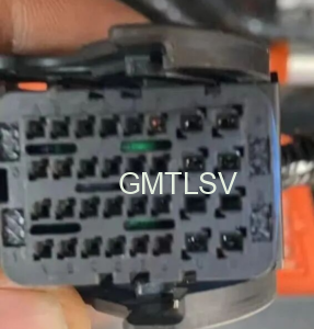
① Low voltage harness connector problem: the connector is loose, the pin is withdrawn, and the pin is reversed, resulting in intermittent interruption of communication;
② Vehicle charging associated controller is abnormal: BMS and VCU are faulty, and charging enable and charging interaction messages are not sent normally.
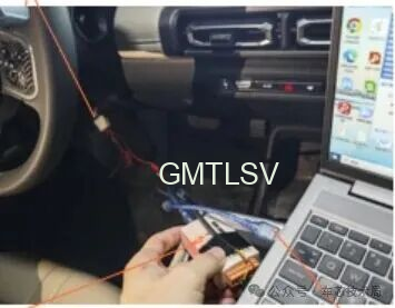
Simple judgment: use the CANtest device to capture the bus message and observe whether there is a BMS charging instruction. There is no message, the fault is at the vehicle end, and there is no need to disassemble the OBC.
- Faults of charger software
The hardware circuit is normal, but the communication function fails, mostly due to software problems:
- Program task stuck, underlying logic BUG;
2.The CAN controller fails to be powered on and initialized, and works in an abnormal mode;
3.CAN transceiver SPI communication interaction is abnormal;
- The message trigger conditions are not met: K15/30 power supply detection is abnormal, and the internal fault flag bit is locked to send the message.
Handling method: If the hardware detection is normal, you can try to rewrite the controller program for retest/or restart the retest after power off.
- Charger hardware CAN circuit fault
The hardware is the high-frequency fault point of after-sales disassembly, which is divided into two circuits:
① CAN circuit of external interface board: breakdown failure of CAN magnetic bead and TVS tube electrostatic protection device (lightning strike and external high and low voltage series current are most likely to be damaged);
② Main board core CAN circuit: CAN transceiver chip is damaged, DSP master control is abnormal, and auxiliary power supply of CAN module is lost.
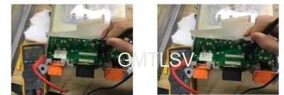
Measurement: measure the connection and disconnection of CAN-H and CAN-L lines in the power-off state; Power on to detect the power supply voltage of CAN chip.
Standardized after-sales troubleshooting sequence
1.Appearance inspection: check whether there is water, looseness or pin deformation in the low-voltage plug of the whole vehicle;
2.Message monitoring: connect CAN acquisition equipment and confirm whether BMS/VCU outputs charging interaction instructions;
- Boundary distinction: no message for the whole vehicle → repair the whole vehicle; The whole vehicle message is normal, and the OBC body is locked;
- Hardware measurement: detect CAN port protection device, chip power supply and CAN bus voltage difference;
- Software verification: if the hardware is normal, refresh the program to test the communication function.
Maintenance reminder
- Do not replace the OBC directly as soon as the communication fault is reported. Half of the faults come from external nodes: poor contact of the vehicle harness connector;
- In rainy days and outdoor parking, focus on checking the CAN interface. External high and low voltage series current and electrostatic breakdown are typical hidden faults;
- Intermittent communication fault is difficult to reproduce in static state. Priority should be given to checking pin contact and power supply stability. It can be verified whether intermittent recurrence occurs when driving on bad roads and bumpy roads.


