Low-Voltage AC, Low-Voltage PMSM, and High-Voltage PMSM
If you’ve ever spec’d a motor controller by just matching the kW rating—like picking a 15 kW drive for a 15 kW motor—congratulations, you’ve done exactly what gets field engineers called back to the site on weekends.
Here’s the thing: a motor controller isn’t a USB charger. It’s an inverter + control algorithm + protection system rolled into one box. Sizing it correctly comes down to three questions:
- Can the voltage handle the bus, including spikes?
- Can the current handle the load, without melting?
- Does the control strategy actually speak the motor’s language?
Let’s walk through three real-world scenarios the way I’d explain them to a junior engineer over coffee: a 48V low-voltage AC fan, a 96V 15 kW PMSM for an e-motorcycle, and a 360V high-voltage PMSM for an EV or industrial servo.
First, Two Currents You Must NOT Confuse
Every controller datasheet talks about current. But which one?
| What it is | Where it flows | Formula | |
| DC Bus Current (I_bus) | Average current from battery / power supply | The fat DC cable into the controller | I_bus ≈ P_mech / (η · V_bus) |
| Phase Current (I_phase,rms) | AC current in each motor winding | The three wires to U, V, W | I_phase,rms ≈ T / K_t |
Key takeaway: Controller “kW” ratings are marketing. Amps and volts are engineering.
Scenario 1: Low-Voltage AC Motor (48V / 800W Fan or Pump)
“AC motor” here usually means a small induction or BLDC/PMSM running on a basic V/F or FOC driver.
Example calculation
800W output, 48V supply, system efficiency 92%:
I_bus = 800 / (48 × 0.92) ≈ 18 A
If it’s a PMSM with Kt = 0.11 N·m/A and you need 2 N·m of torque:
I_phase,rms = 2 / 0.11 ≈ 18 A
Add 30% margin for starting surges → size for ~23 A per phase.
Voltage rating
48V systems often charge to 54V, and switching transients add spikes. Rule of thumb:
V_device ≥ 1.25 ~ 1.5 × V_bus,max
54 × 1.5 ≈ 81V → 80V or 100V MOSFETs are the sweet spot. A 60V part here is a ticking time bomb.
What to look for
- Devices: Low-voltage MOSFETs
- Control: V/F is fine for fans/pumps; FOC if you want smoothness and efficiency
- Controller spec: 48V class, continuous 20–25A DC
- Watch out for: Cheap “800W universal boards” that don’t list actual current ratings
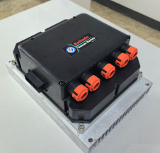
Scenario 2: Low-Voltage PMSM (96V / 15 kW E-Motorcycle, AGV, Light Truck)
This is where people get burned. Literally.
DC bus current
15 kW, 96V nominal, 88% system efficiency:
I_bus = 15000 / (96 × 0.88) ≈ 178 A
But batteries sag. At 84V minimum:
I_bus = 15000 / (84 × 0.88) ≈ 203 A
So your BMS, cables, and fuses need to handle 180–200A continuous, not the 156A you’d get from a naive “15 kW ÷ 96V” calculation.
Phase current
Low-voltage PMSMs have high power factor, so phase current tracks DC current closely:
I_phase,rms ≈ 170 ~ 185 A
Peak (acceleration, hill climb) can be 2–3×: 350–550A for several seconds.
Voltage rating
96V system, fully charged: ~112V. Regenerative braking adds spikes.
112 × 1.5 ≈ 168 V
- 120V MOSFETs: No
- 150V MOSFETs: Marginal but workable
- 200V MOSFETs: Recommended
Why you need parallel FETs
A “100A” MOSFET is rated at 25°C case temperature. In a real air-cooled controller at 80°C, you might only get 50–60A usable.
With 185A phase current, each switch sees ~0.5 × 185 ≈ 92A RMS. So you parallel 2–3 FETs per phase; total 12–18 power devices in the bridge.
Conduction loss reality check
Two 150V FETs in parallel, 5 mΩ each at hot temperature:
R_phase,on = 5 mΩ / 2 = 2.5 mΩ
P_cond,phase = 185² × 0.0025 ≈ 85.6 W
Three phases → ~257W just in conduction. Add switching losses → 400–700W total inverter loss. That’s a lot of heat to move with air cooling.
What to look for
| Parameter | Value |
| Input range | 80–112V DC, transient ≥120V |
| Continuous DC | 180–200A |
| Continuous phase | 170–190A RMS |
| Peak phase | 400–600A / 10–30s |
| Devices | 150V or 200V MOSFETs, 2–3 parallel per phase |
| Control | FOC with MTPA and field weakening |
| Feedback | Hall / encoder / resolver (no sensorless for traction!) |
| Cooling | Large heatsink + fan; liquid if running continuous |
Lesson: Low-voltage PMSMs aren’t “easier” because the voltage is low. They’re harder because the currents are brutal.
Scenario 3: High-Voltage PMSM (360V / 30 kW EV, Industrial Servo)
High-voltage systems flip the problem. Currents are manageable, but voltage, safety, and insulation dominate.
DC bus current
30 kW, 360V bus, 93% efficiency:
I_bus = 30000 / (360 × 0.93) ≈ 90 A
Compare that to the same 30 kW at 96V: ~336A. That’s the magic of high voltage—same power, a fraction of the current.
Phase current
I_phase,rms ≈ T / Kt
For a 30 kW HV motor, expect 50–80A RMS nominal, with peaks of 100–160A. Much more civilized than the low-voltage case.
Voltage rating
360V battery, regen spikes, line transients:
V_device ≥ 1.5 × 410 V ≈ 615 V
→ 1200V IGBTs or 750V/1200V SiC MOSFETs. For 800V automotive platforms: 1200V SiC is the only sensible choice.
What to look for
| Parameter | Value |
| Input range | 250–450V DC (or 500–900V for 800V systems) |
| Continuous phase | 80–100A RMS |
| Peak phase | 160–200A / 10s |
| Devices | 1200V IGBT or SiC modules |
| Control | FOC + safety-rated STO (Safe Torque Off) |
| Feedback | Resolver (automotive) or high-res encoder (industrial) |
| Communication | CAN/CANopen (automotive), EtherCAT/Profinet (industrial) |
| Cooling | Liquid cooling standard |
| Protection | IP67, isolation monitoring, pre-charge, contactor control |
Lesson: HV systems trade current stress for voltage stress. Your concerns shift from “how do I not melt the copper” to “how do I not kill someone or violate ISO 26262.”
Quick Comparison Table
| Type | Typical System | Current Profile | Power Devices | Control Focus |
| Low-Voltage AC | 48V 800W fan/pump | ~18A DC, ~18A phase | 80/100V MOSFETs | V/F or basic FOC |
| Low-Voltage PMSM | 96V 15kW e-moto/AGV | ~180A DC, ~185A phase | 150/200V MOSFETs, heavily paralleled | FOC + encoder + field weakening |
| High-Voltage PMSM | 360V 30kW EV/servo | ~90A DC, ~70A phase | 1200V IGBT or SiC | FOC + safety + communication + regen |
The Engineer’s Cheat Sheet
- Calculate I_bus at minimum battery voltage → size cables, fuses, BMS.
- Calculate I_phase,rms from torque and Kt → size inverter switches.
- Multiply by 1.2–1.5× margin for continuous, 2–3× for peak.
- Pick device voltage ≥ 1.5× maximum bus voltage (including regen spikes).
- Check junction temperature with real thermal resistance, not catalog fantasy.
- If Tj > 150°C, parallel more, cool better, or switch slower.
Final Thought
A controller that says “15 kW” on the label tells you almost nothing. A controller that says “96V, 200A DC continuous, 180A RMS phase, 600A peak / 10s, 200V MOSFET, FOC, IP65, CAN” tells you everything.
Spec like an engineer, not like a catalog browser.