If you’ve ever designed a controller for a low-speed EV—golf cart, resort shuttle, warehouse tugger—you’ve probably seen this complaint:
“Full charge, it climbs fine. After 20 minutes, it just gives up on the same hill.”
The motor isn’t broken. The controller isn’t lying. It’s field weakening, and more specifically, the lack of voltage headroom to do it properly.
This post explains what field weakening actually is, why it exists, and how to tune it without blowing up your magnets.

The Core Problem: Back-EMF Eats Your Voltage
A PMSM (Permanent Magnet Synchronous Motor) generates torque from the interaction between the rotor’s permanent magnets and the stator’s rotating magnetic field. But there’s a catch: the faster the rotor spins, the more back-EMF it generates.
Back-EMF is a voltage produced by the magnets moving past the stator windings. It opposes the voltage your controller is trying to apply. The net voltage available to push current is:

At low speed, back-EMF is small, so almost all the battery voltage is available to push current → lots of torque.
At high speed, back-EMF is large. If the battery is also low, V_available shrinks to almost nothing. No voltage → no current → no torque. That’s why your cart can’t climb the hill at the end of a run.
Why Can’t You Just “Give It More Current”?
You can’t push more current without voltage. Ohm’s law doesn’t care about your feelings:

Where Z is the motor impedance at that frequency. If V_available is near zero, current is near zero, no matter how big your MOSFETs are.
This is why a “300 A controller” still can’t save you when the battery is at 42 V and you’re asking for high speed + high torque simultaneously. The current capability is there, but the voltage headroom isn’t.
What Is Field Weakening, Really?
In a PMSM, the rotor’s magnetic field is fixed—permanent magnets don’t just “turn down.” So as speed increases and back-EMF rises, you have a problem: the controller’s output voltage is capped by the battery.
Field weakening is a trick: use stator current to cancel part of the rotor’s magnetic field.
In FOC (Field-Oriented Control), stator current is split into two components:
| Component | Does |
| Iq | Produces torque (the useful one) |
| Id | Produces magnetic field along the rotor axis |
In normal operation, $I_d = 0$. All current goes to torque.
In field weakening, you deliberately make $I_d$ negative—the stator creates a magnetic field that opposes the rotor’s permanent magnets. Net flux drops → back-EMF drops → the same battery voltage can now sustain a higher speed.
That’s why it’s called field weakening: you weaken the total magnetic field to trade torque for speed.

The Trade-Off (There’s Always One)
Here’s the catch. The total stator current has a hard limit:
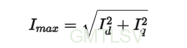
When you push $I_d$ negative for field weakening, that current can’t be used for torque anymore. It’s consumed by the weakening function. So:
- $I_d = 0$ → all current available for torque (maximum pull)
- $I_d = -20$ A → 20 A of your budget is gone, $I_q$ must shrink → torque drops
Field weakening is literally a tax on your torque budget.
The deeper you go, the less torque you have. At some point, you’re spinning fast but can’t even push the cart forward on flat ground.
The Voltage Limit Circle
To visualize this, engineers use the “voltage limit circle”:
Vmax (full battery)
.——–.
/ \
| .——. | ← operating point
| / \|
| | |
\ \ \
‘–‘——–‘
Vmax (low battery)
.–.
/ | ← much smaller circle
| o | operating point may fall OUTSIDE
\ |
‘–‘
The circle shrinks as battery voltage drops. When your required operating point (speed × torque) falls outside the circle, the controller simply can’t reach it. No algorithm can break physics.
How to Tune Field Weakening (Practical Guide)
Method 1: Voltage Feedback (Recommended)
This is the industry-standard approach. Don’t set $I_d$ based on speed—set it based on how close you are to the voltage limit.
// After current loop calculates Vd, Vq:
V_used = sqrt(Vd^2 + Vq^2);
V_max = V_dc / sqrt(3) * 0.95; // 5% margin
v_error = V_max – V_used;
if (v_error < 0) {
Id_fw -= Ki_fw * v_error; // push Id negative
Id_fw = clamp(Id_fw, -Id_max, 0);
}
Key rules:
- Weak field loop must be slower than current loop (50–200 Hz vs 1–5 kHz)
- Id_max≤ 30–50% of rated current for surface-mount PMSM
- Margin 5–8% is typical; too small = oscillation, too large = weak performance
Method 2: Speed Lookup Table (Simple but Fragile)
if (speed < 0.9 * base_speed)
Id_ref = 0;else
Id_ref = -k_fw * (speed – base_speed);
Problem: battery voltage changes. A table tuned for 54 V will be wrong at 42 V. Don’t use this alone on a low-voltage system.
Method 3: Analytical (Parameters Required)
Solve the intersection of the voltage ellipse and current circle. Accurate if your motor parameters are correct. In practice, use this as feedforward and let voltage feedback correct the error.
Common Mistakes
| Symptom | Cause |
| Jerky transition into field weakening | Hard switch from Id=0 to Id<0, no hysteresis |
| Motor stalls on hill at low SoC | Voltage circle too small; need higher battery voltage or lower base speed |
| Magnets demagnetized after one season | Id too negative + high temperature + sustained operation |
| High-speed acceleration triggers overcurrent | Field weakening too slow, voltage saturates before Id responds |
Design Takeaways
- Specify battery voltage for the worst case, not the best. If your cart must climb a 15% grade at 20 km/h with the battery at 20% SoC, design for that voltage—not the full-charge number.
- Lower base speed = less need for field weakening. Use a higher pole-count motor or a gear reduction. A 10-pole motor at 3000 rpm has a lower base speed than a 6-pole at the same rpm, leaving more headroom.
- 72 V systems suffer less. Double the voltage → double the voltage circle → half the field weakening needed for the same speed. That’s why commercial shuttles are moving to 72 V.
- Field weakening is not a performance feature. It’s a coping mechanism. If your application spends most of its time in field weakening, you probably undersized the battery voltage or over-geared the drivetrain.
The Bottom Line
Field weakening on PMSM is simple in concept: push negative direct-axis current to cancel the rotor flux, reducing back-EMF so the motor can spin faster on limited voltage.
But in practice, it’s a careful balancing act between:
- Voltage headroom (battery state)
- Current budget (thermal limits)
- Torque demand (driver expectations)
- Magnet safety (temperature + demagnetization risk)
If your golf cart can’t climb the hill at the end of a run, now you know why. And more importantly, you know what to change: more voltage, not more current.