

Vehicle reported insulation failure, limited power, unable to charge? Naked eye inspection can only judge the surface damage caused by moisture, and the accurate insulation resistance value must rely on professional insulation resistance tester.
Use the insulation detector to complete the insulation detection of high-voltage circuit, understand the instrument, standardize the wiring, and fully cover the safety measurement.
Necessary tools and safety protection for detection
1.List of tools
① One set of insulation resistance tester (host, test probe, test clip and accessories);
② One pair of high-voltage insulation protective gloves;
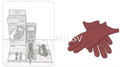
Front safety red line
- The vehicle must be completely powered off, pull out the smart key, and wait for the high-voltage capacitor to discharge completely for 10 minutes;
- Wear insulating gloves throughout the whole process, and do not touch the metal parts of high-voltage terminals and test probes with bare hands;
- Only use CAT III 1000V/CAT IV 600V matching probe to avoid electric shock and damage to the instrument;
- If the voltage of the detection circuit is more than 30 V, the instrument will trigger the high voltage alarm, and it is forbidden to continue the test, and the power will be cut off first;
- It is forbidden to carry out high-voltage insulation measurement in humid and waterlogged environment to prevent short circuit and leakage.
Analysis of instrument key, terminal and gear
Description of the top function key
1.Access: switch various measurement function gears
- Storage: Save the measured data of this insulation/grounding resistance and retrieve the historical storage records.
3.Comparison: Set the insulation qualified/failed threshold, and make qualified judgment with the test.
- locking: locking the current measurement data; Press and hold to clear all stored records of the instrument
- Backlight key (sun icon): Turn on the screen backlight, and it will automatically go out without operation for 2 minutes.
- Test button: core measurement button, long press the output high voltage to complete the insulation detection; Press ahead to lock test mode
Bottom Input Terminal
- Ω terminal: special input port for common resistance measurement
2.COM terminal: public return terminal, which must be connected in the whole process of measurement
- Insulated V terminal: special input port for insulated high voltage and voltage measurement
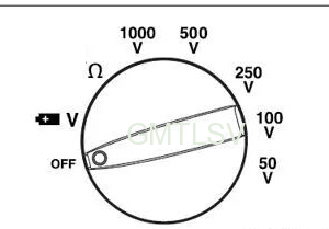
Rotary switch gear function
Display identification
1.Common Icon Meaning
-Test: The meter is outputting high voltage for insulation measurement
-Locked: the current value is locked and saved
-PI/DAR: polarization index, dielectric absorption test mode
-Lightning symbol: dangerous voltage alarm, circuit voltage ≥ 30V
-batt: The battery of the instrument is low and needs to be replaced.
->: The measured value exceeds the current upper range limit.
- Unit identification:
VAC voltage, VDC voltage, kMΩ/MΩ/GΩ insulation resistance unit
3.Error code
-batt: The battery is low and cannot be tested normally.
->: The measured insulation resistance exceeds the maximum range of the instrument.
-CAL Err: The instrument calibration is invalid and needs to be returned to the factory for calibration.
Complete operation steps for standard measurement of insulation resistance
Step 1: Wiring of meter probe
1.Insert the black public probe into the COM terminal of the instrument;
2.Insert the red high-voltage test probe into the insulated V terminal;
3.One end of the probe is connected to the high-voltage tested circuit (total positive and total negative of the battery, high-voltage terminal of the motor, high-voltage terminal of the OBC, etc.); the other end of the probe is connected to the vehicle chassis, battery pack shell and other vehicle grounding shells.
Step 2: Select the test voltage gear
According to the rated voltage of the vehicle high-voltage system, the rotary switch switches the corresponding insulation test voltage:
-Low-speed low-voltage energy storage system: 50V/100V
-Conventional power battery pack for passenger car: 500V
-Large commercial vehicle high voltage platform: 1000V
Step 3: Pre-circuit voltage self-check
After the probe is connected, the instrument automatically detects the circuit voltage:
- The screen displays — — –: there is no residual high voltage in the circuit, and the test can be started normally;
- Lightning warning symbol + high voltage value pops up on the screen: if the residual voltage of the circuit is > 30V, disconnect the probe immediately and wait for the vehicle to fully discharge before operation.
Step 4: Start insulation measurement
- Press and hold the “Test” button on the panel, and the instrument will output high voltage;
2.The upper part of the screen displays the current output test voltage, and the main screen refreshes the insulation resistance value in real time, in MΩ/GΩ;
- If the resistance value is greater than upper limit of the gear range, the screen displays the > symbol, indicating that the insulation state is excellent;
- After releasing the test button, the probe will remain connected to the test point, the tested circuit will automatically discharge through the instrument, and the screen will retain the final reading.
Step 5: Data storage and determination
- After the measurement is completed, press the “Save” key to save the current insulation value;
- Set the national standard insulation threshold (new energy vehicle standard ≥ 100Ω/V) through the “Comparison” key in advance, and the screen will automatically prompt whether it meets the standard during measurement;
- If you need to keep the data, you can press “Lock” to freeze the screen reading for easy photo recording.
Measurement result judgment and fault location
- Eligibility criteria
High voltage insulation resistance of the whole vehicle ≥ 500Ω/V
Example: 500V battery pack, insulation resistance ≥ 0.25 MΩ is normal; The lower the value, the higher the risk of leakage.
- Fault analysis of numerical correspondence
-Resistance value ≥ 100MΩ: excellent insulation, no electric leakage, and the insulation fault reported by the instrument is the accidental false alarm of the software;
-< 0.1MΩ: serious insulation damage, high voltage harness, battery pack, electric control internal leakage, do not drive with power on, disassemble and repair immediately.
Routine maintenance of instrument
- Replace the battery as soon as possible when low battery prompts batt. Low voltage will cause distortion of insulation measurement data;
2.Turn the rotary switch to the OFF position after the measurement to avoid long-term power consumption of the instrument;
- If the insulation layer of the meter pen is cracked or damaged, it is forbidden to continue to use, and there is a risk of electric shock;
4.Check the CAL calibration status before each test, and do not use the CAL Err code for high voltage safety test;
5.Be sure to release the test key after the measurement is completed, and wait for the circuit to discharge completely before removing the probe.
Insulation failure is directly related to the safety of the vehicle personnel and the life of the vehicle.
From safety protection to measurement steps, and then to result judgment, each link is based on actual combat experience.
Follow the steps: power off the vehicle, wear gloves, connect the meter probe, select the right voltage gear, check the circuit voltage, start the insulation measurement, store the data and judge according to the standard. If you find that the resistance is below 0.1MΩ, congratulations, the problem has been found, but do not rush to power on, be sure to do a good job of discharge and quarantine before disassembly and maintenance. Also, don’t forget the daily maintenance of the meter: battery level, probe insulation status, calibration status, these details determine whether your measurement results are reliable.


