

Have you ever had the experience of confidently taking out a multimeter to verify whether the CAN bus is normal at the vehicle commissioning site, but the number popping up on the screen makes you confused-not the familiar 60Ω, but 140Ω, 180Ω, or even higher! You begin to suspect that the instrument is broken or that there is a problem with the wiring, but after repeated measurements, it is still fruitless.
Don’t worry, what you measure is not the fault, but the system status.
Behind this lies the core logic of CAN bus design.
As the core of the vehicle network, CAN bus is not simply two wires, but a complex system composed of multiple nodes, terminal resistors and various protection devices.
Let’s disassemble the truth of “uncertainty” and avoid the most common measurement errors.
The first time many people take a multimeter to measure the CAN bus, they will have doubts:
- Design value:120Ω
- Measured values:140 Ω, 150 Ω or more
- First reaction:Is the resistance broken? Is it less loaded?
You don’t detect a fault, you detect a “system state”.
The “real structure” of CAN
The CAN bus is not a wire, it is a complete network.
The typical structure is as follows:

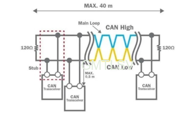
CAN bus resistance = 120Ω terminals at both ends + resistance of all ECUs in the middle connected in parallel to a twisted pair
What is the theoretical value?
Let’s first make the cleanest situation clear:
One 120Ω at each end:
120Ω || 120Ω
Equivalent results:
60Ω
Many people regard “120Ω” as the measurement target of the whole vehicle, which is the first misunderstanding.
In fact:
| Measurement mode | Theoretical results |
| Single-ended termination resistor | 120Ω |
| CANH-CANL whole network | 60Ω |
Field measurement method
Many engineers measure it like this:
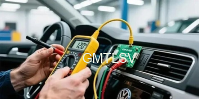
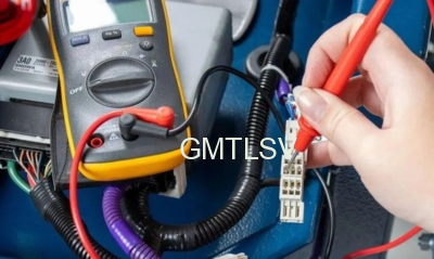
You will find a key problem:
The car is a “structured system”, not a laboratory resistor box.
Where does the resistance value of 140 Ω or more come from?
This value usually comes from three types of reasons:
- A termination resistor is “not really connected”
For exampl:
- VCU terminal is not powered on
- TBOX is powered down
- OBD interface internal terminal not connected
Resul:
120Ω becomes “half network”
- The network is in a “semi-powered off state”
Many people overlook one point:
When the CAN transceiver is not powered on, the CAN resistance model exists.
At this tim:
- ESD device
- Protection Diode
- Internal leakage path
Will participate in the measurement.
- You’re measuring “mixed impedance,” not pure resistance.
Also in the CAN network:
- Common mode inductance
- TVS tube
- ESD discharge path
- Internal structure of MCU
These may conduct under the low voltage test of the multimeter
True equivalent model
We can simplify the whole car can into:
120Ω
+ 120Ω
+ Leakage path
+ Half-on protection device
+ Transceiver not powered
The result will be:
Drift between 60Ω → 120Ω → 140Ω → 180Ω
A real engineering case
One project:
- VCU + TBOX + OBD three-node CAN
- The BOM is absolutely correct
- Resistance 100% 120Ω
However, the whole vehicle measurement:
145Ω
Later, the investigation found that:
✔ TBOX is not powered up
✔ OBD internal terminal not connected
✔ One ECU enters sleep mode
Conclusion:
It’s not that the resistance is wrong, but that the network is “incomplete” when it is measured.
Correct measurement method
1: Complete vehicle power-off test CANH-CANL
Reques:
- All ECUs are de-energized
- The bus is completely static
Normal result: ≈ 60Ω
2: Node-by-node plugging method
The most reliable method in engineering:
- Pull out TBOX → see the change
- Pull out VCU → see the change
- Pull out OBD → see the change
Resul:
Resistance “returns to 120Ω” step by step
Judgement
CAN measurement is not a resistance measurement, but a verification that the topology is complete
- 60Ω → Double terminal OK
- 120Ω → one less terminal
- 140Ω ~ 180Ω → Network Incomplete/Half Power-Up/Virtual Path
- ∞→ broken line
Back to the original question-why is the CAN bus resistance always measured incorrectly at 120Ω?
The answer is really simple: you’re not measuring a resistance, you’re assessing the integrity of a dynamic system.
60 Ω is the “identity card” of the ideal network, while 140 Ω and 180 Ω are the “incomplete” signal lights of the system. When you master the correct method (vehicle power-off, node-by-node plugging), you can accurately judge which node is offline and which terminal fails, rather than blindly replacing hardware.
So, the next time you encounter an “uncertain” situation, you might as well change your way of thinking: every abnormal reading is the system “telling you” its true state.
Remember, the core of CAN measurement is not numerical value, but topology verification. By mastering this logic, you can change from a passive troubleshooter to an active diagnostician, making the complex CAN network clear and controllable.


